Introduction to RF Level Measurement
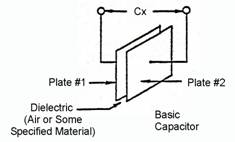
ForwardToday, the need for accurate, reliable level measurement and control is nearly universal in the process industries. Engineers and managers are under increasing pressure to operate their plants more efficiently, to minimize labor and material costs, to ensure on-time delivery of product, and to eliminate spills of even marginally hazardous materials. A wide variety of mechanical, electromechanical and pure electronic technologies have been used for level measurement. These include: floats, displacers, paddle wheels, yo-yos, tuning forks, differential pressure (DP), bubblers, pressure, strain gauges, load cells, resistance tape, sonic, ultrasonic, conductivity, thermal, nuclear, microwave, radar and capacitance. Pure electronic level measurement technology offers considerable advantages: its no-moving part designs are more reliable, are less prone to clogging and the other effects of aggressive process materials, and they require considerably less maintenance. One of the most successful electronic technologies used for level measurement has been “capacitance”. In this handbook we will examine the use of capacitance technology as a method for measuring and controlling the level of process materials IntroductionCapacitance level measurement has progressed from its original design, sometimes called conventional or straight capacitance, through a series of enhancements to the refinement known as “RF Impedance”. Princo’s NULL-KOTE™ circuitry is the most advanced form of RF Impedance available today. In order to understand the need for “enhanced capacitance technology”, lets take a brief look at conventional capacitance systems. A classic textbook parallel plate capacitor is shown in Fig. 1. Its capacitive value depends upon the area of each plate, the distance between the plates and dielectric of whatever material occupies the space between the plates.
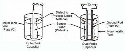
Figure 1 In a conventional capacitance system, a metallic, rod-like sensing probe is placed in the vessel. As the process material rises and falls, the system responds to capacitive changes measured by the sensing probe. With non-conductive materials, the sensing probe becomes one plate of a capacitor, the metal vessel wall (Fig. 2), or other suitable ground (Fig. 3), becomes the second plate, and the process material becomes the dielectric medium. As the vessel is filled, air, with its dielectric constant of 1, is displaced by the process material with a higher dielectric constant, and the capacitive output of the probe increases.
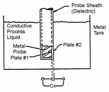
Figure 2 Figure 3 Both conventional and enhanced capacitance systems can work well with non-conductive, clean materials such as hydrocarbons, solvents, vegetable oils, etc. provided that these materials have stable dielectric constants. However, conventional capacitance works well with conductive materials only as long as there is never any possibility that a conductive coating may build up on the sensing probe. When we are dealing with conductive process materials, the sensing probe is always covered with an insulating sheath. The conductive process material couples the metal vessel wall (or other suitable ground) directly to the probe sheath (Fig. 4). Since the probe sheath is constant for a given installation, the system responds identically to all conductive materials. This makes capacitance an excellent method to measure the level of conductive process materials.
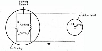
Figure 4 As mentioned before, conventional capacitance systems will exhibit unacceptable measurement errors if the process material is conductive (such as brine, slurries, waste water, etc.) and tends to build up on (coat) the sensing probe. Let’s look at an application involving a conductive liquid which builds up on the sensor probe: As the material rises for the first time on a clean probe, the output from the system is correct. But when the material level falls, a conductive coating clings to the probe. A conventional capacitance system cannot differentiate between the conductive coating and the actual process level. Therefore, the output of the system is incorrect. As long as this conductive coating is present on the probe, accurate measurement with conventional capacitance is impossible. Enhanced capacitance level measurement Several methods of enhanced capacitance level measurement have been developed to counteract the problem of conductive probe coatings. These systems are collectively referred to as “RF” level instruments. One type of enhancement uses high frequency (over 1 MHz) operating circuits. This type of system relies on the “skin effect” of the high frequency sensing circuit to render the probe somewhat less responsive to conductive coatings. Such systems are not used on difficult applications. Some manufacturers try to use high frequency to counteract conductive coatings in both point and continuous level systems. This method works well only in less demanding applications. Another method, which Princo Instruments refers to as “NULL-KOTE™ RF Impedance”, has a far greater range of application and success. NULL-KOTE™, is a trademark name of Princo Instruments, Inc’s proprietary circuit designs. These designs enable Princo RF level instruments to function reliably and accurately even when the material being measured deposits a conductive coating build-up on the sensing probe. There are actually two types of NULL-KOTE™ circuits. One type is for single point controllers and a second type is for level transmitters and multiple point controllers. For single point controllers Princo Instruments employs a driven guard element to null out the effect of conductive coatings. We will examine this type of NULL-KOTE™ under "RF Impedance Point Level Controls". The method used to cancel the effect of conductive coatings in continuous and multiple point applications involves the measurement of impedance, in addition to capacitance measurement. This type of circuit will be discussed under "Multi-Point Level Controllers" and "Presence/Absence Detectors". The latest, most effective refinement of this type of level measurement technique is Princo’s unique Digital NULL-KOTE™ circuitry used in the SMART l™ level transmitter. Here, digital signals that represent the coating and the process material level are fed to a microprocessor. Special software, developed to cancel out the effect of the probe coating, calculates the actual level of the process material. RF Impedance Point Level ControlsDefinitionPoint level (single point) controls are devices used to detect when the level of the process material being measured reaches a predetermined height (or point) in the vessel. The device responds to a level being detected by changing its output state, usually by switching a relay. Accordingly, this type of device is referred to in the trade as a “level switch”. The relay activation is usually used to trigger an alarm (audible and/or visible), and/or to activate a pump or a valve, so as to control the level being sensed. TheoryTo understand the theory of point level measurement using an RF impedance sensing technique, a basic understanding of conventional capacitance point level controls is required first. In a conventional capacitance system, the sensing probe consists of a conductive metal rod covered by a Teflon® insulating sheath. The preferred mounting is horizontally into the vessel through the side wall, at a height at which level detection is required. With only air (no product) in the vessel, there exists a capacitance between the sensor rod and the metal vessel wall (the insulating media being the air @ K=1.0, in the empty vessel). When the level of the process material rises and makes contact with the sensor, the capacitance between the sensor rod and the vessel wall increases significantly. The capacitance change is detected by the electronics, which causes a relay to switch in response to it. From the discussion above, it looks as if conventional capacitance technology offers a workable approach to point level control. For some applications this is true. However, consider what happens if a conductive process residue or build-up adheres to the sensor as is often the case with industrial applications (Fig. 5 a,b). This conductive coating electrically couples the active sensing element to the grounded vessel wall, resulting in a very large increase in the capacitance sensed by the probe and produces a false level indication (always indicating high level or presence of material).
Figure 5a
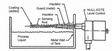
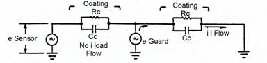
Figure 5b The solution is NULL-KOTE™ RF Impedance Point Level Sensing. This involves the use of a special probe, with a “guarded” sensor, in which an exposed guard element is built into the sensing probe. This guard is physically located between the active measuring element and the vessel wall (Fig. 6a). The drive to the guard is of the same voltage, frequency, and phase as the RF signal supplied to the active measuring element. Even with a coating adhering to the sensor, no current flows between measure element and the guard because they are at the same potential. Current flows only from the guard element to the vessel wall, and this current is not measured (Fig. 6b). However, when the process material comes up and makes contact with the active measurement element, current flows from it, through the process material to the vessel wall, and the level is accurately detected. Over the past two decades, RF impedance sensing has been proven to be the technology of choice, even for the most difficult point level requirements encountered in the harsh industrial process control environment.
Figure 6a
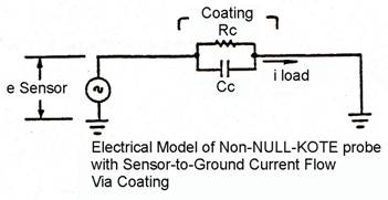
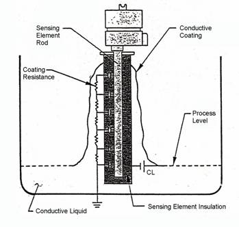
Figure 6b Continuous Level TransmittersDefinitionContinuous level transmitters are devices used to measure the amount of process material contained in the vessel. They produce an output current signal, usually 4 to 20 milliamperes, which is directly proportional to the level. The signal is connected to other devices, such as computers, programmable logic controllers (plc), meters, recorders and/or controllers or for monitoring and/or controlling the process level. TheoryIn very basic terms, a continuous RF impedance level measurement system is merely a capacitor created in a vessel with a long conductive probe as one plate and a ground reference element or the tank wall as the other plate. The amount of material covering the probe determines the amount of capacitance change measured by the transmitter. The approach used differs somewhat dependent on whether the process material is electrically conductive or insulating. These two classes of material will be considered separately. Non-Conductive / Insulating Process MaterialsProcess materials, such as hydrocarbons, solvents, vegetable oils, etc. are electrically non-conductive and typically have a conductivity of less than 5 microsiemens per centimeter. Generally, with any non-conductive material, it is desirable to maximize the probe response. This insures the highest possible accuracy and stability for the system. To maximize the. signal when measuring liquids with low dielectric constants, a ground plate or rod is placed close to the sensing probe. Performance is improved since the distance between the plates is an inverse function of capacitance. That is, reducing the distance between the plates causes an increase in capacitance. Another common technique is to surround the probe with a concentric tube at ground potential. The use of a parallel ground rod or concentric ground tube is also common in applications where the distance between the probe and the outer wall varies as a function of the container’s depth, such as in the case of a horizontal cylindrical tank. Failure to use a proper ground reference in this type of tank would result in non-linear signal output for equal incremental changes in liquid level. With non-conductive materials the capacitive output from the probe depends upon the dielectric of the process material. Therefore, the materials dielectric constant must be stable, as changes in dielectric constant due to temperature or composition will result in an invalid change in the indicated level. Conductive Process MaterialsProcess materials containing water (aqueous based) such as slurries, acids, solutions, waste water, caustics, etc. are electrically conductive and typically have a conductivity in excess of 100 microsiemens per centimeter. In this case, the sensing probe consists of a conductive metal element covered by Teflon® or Kynar® insulation. The metal element acts as one plate of the capacitor, the insulation on the probe is the dielectric material and the process material acts as the ground plate. This is true, provided the material is in electrical contact with the grounded metal wall of the vessel or, in the case of non-metal vessel, a suitable metal or insulated ground reference. When air in the empty vessel is displaced by the conductive process material, the capacitance change measured is the saturation (maximum) capacitance of the insulation sheath which is immersed in the grounded process material. Accordingly, the measured capacitance is a function of only the stable insulation sheath of the probe and the process level surrounding it. The measurement is unaffected by changes in the temperature or composition of a conductive process material. Because the material acts as the second plate of the capacitor, the indicated level will be linear, independent of the shape of the wall of the vessel, i.e. horizontal cylindrical or spherical tanks. The Need for NULL-KOTE™In a conventional capacitance level transmitter, a significant level measurement error will occur, if the process material is conductive and tends to build up a coating on the level sensing probe. This is a common problem encountered in many industrial level applications. The problem occurs because the conductive coating causes the instrument to measure the extra capacitance as well as the resistance of the coating. This produces an indicated level higher than the actual level in the tank. Consider a typical example: a viscous, conductive liquid is rising on a perfectly clean probe. The increasing milliamp output from the transmitter is correct and proportional to the change in level. After reaching some maximum level, the process liquid begins to recede. As the level drops and leaves a coating (Fig. 7), the change in meter reading is no longer proportional to the change in level, due to the conductive coating. In fact, it may be grossly incorrect. Once the probe is coated, accurate measurements are no longer possible with a system which measures capacitance only.
Figure 7 RF impedance sensing employing NULL-KOTE™ circuitry solves this problem. It has been observed that Mother Nature forms all probe coatings alike: that is, the coating is equivalent to a network with a large number of series resistors, plus an equal number of incremental capacitors shunted between the resistor junctions and a common ground plane. The Rc and Cc in this network represents the resistive and capacitive components of the process coating. A composite electrical model of all components including coating may be drawn (Fig 8). We also know that the coating related Rc and Cc have a very specific relationship to one another and to the frequency of measurement (Rc=Xcc at Fx).
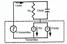
Figure 8 In addition to the resistance and capacitance components due to the coating the instrument also measures the capacitive component due to the actual process material level. Basically, there are two measured variables, capacitance and resistance, and two unknowns, level and coating. Given a mathematical relationship of this type the unknown level can be readily determined. The NULL-KOTE™ circuitry in the RF Impedance sensing transmitter solves the mathematical function electronically (Fig. 9) to produce a 4 to 20mA current output that is proportional only to level and virtually unaffected by the process material coating build-up on the sensing probe.
Figure 9
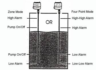
Multi-Point Level ControllersDefinitionMultiple point level controllers are hybrid devices that bridge the gap between point level controllers, with their single on/off control and continuous level transmitters that provide an analog output over the range of level measured. These controllers offer up to four separate alarm points or a zone and 2 alarm (set) points from one system. This type of level instrument offers savings in purchase and installation costs, as well as convenience simplicity of operation. From a single system, a user can field-configure up to four level control points, or two points and one zone. TheoryMultiple point level controllers use exactly the same measurement technique as do continuous transmitters. A single RF probe is mounted from the top of the vessel. The probe is long enough so that it reaches beyond the lowest point in the vessel at which level detection may be required. The RF impedance measurement is identical to that described under "RF Impedance Point Level Controls". Within the controller, the resultant dc signal is supplied to the input of four independent comparators, the outputs of which are used to operate the controller’s relays. CharacteristicsDual FunctionThe unit is a Dual Function controller in that it can operate as a point control with four independent switch points, or as a zone controller, with two additional switch points. As a four-point level controller (Fig. 10), it is ideal for use either in batching operation, or as a multiple point level alarm for applications requiring high alarm, high-high alarm, low alarm and low-low alarm, all operating from a single probe.
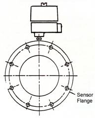
Figure 10 Field CalibrationThese units may be supplied factory pre-calibrated. However, a major advantage of these devices is their field calibration flexibility. Each trip point can easily be set in the field, (i.e. moved up or down in the vessel) by merely making a screwdriver adjustment to the electronics. No mechanical changes, such as relocating a probe are required. Complete calibration in the field is commonly done using a “fill and empty” technique. Presence / Absence DetectorsDescriptionThis device is an RF point sensor for detecting the presence or absence of material in a pipe. The active sensing element is embedded (cast) into a standard ASTM size flange (Fig. 11) to provide obstructionless sensing. Originally designed to provide run-dry protection for positive displacement (progressive cavity) pumps, it is now widely used anywhere full/empty pipeline sensing is required.
Figure 11 TheoryThe basic operation of this device is the same as described previously in "RF Impedance Point Level Controls". However, the Presence/Absence Detector does not use a guarded sensor. The NULL-KOTE™ coating immune feature is achieved in this system by the combination of higher frequency operation (over 1 megahertz) and wide range of sensitivity along with the unique design of the sensor flange. The higher frequency operation produces what is referred to as the “skin effect” phenomenon in the conductive coating. Basically, at these high frequencies, any current flow only occurs on the surface or skin of the coating, causing it to appear as a higher resistance than it might otherwise produce. This tends to make the adverse effect of the conductive coating much less significant. The other aspect used to eliminate the adverse coating effect is the ability to significantly desensitize the unit so that it does not respond to heavy coating, but does respond to the greater volume of process material itself. Although not mentioned previously in this section, both of these coating immune features are not only employed in Presence/Absence Detectors but also come into play in Princo Point Level (Single Point) Controllers as well. |